A compression performance comparison of INSERT BLOCKS manufactured from different materials subjected to an axial fatigue load.
Supporting and the accurate positioning of tooling on a Carbon Dial Table may on occasion require a INSERT BLOCK to be molded within the Dial structure.
The INSERT BLOCK can be manufactured from several materials. The choice of material is dependent on loads applied to the tooling.
To provide insight into the different materials available an analysis was performed on a dowel pin in a hole with a steel insert. INSERT BLOCK materials were FOAM (baseline), CARBON LAMINATE, STEEL, Mic6 ALUMINUM (Typical Dial Table material), and 6061-T6 Aluminum.
Three axial load cases where considered, 200 lbs, 1000 lbs and 6000 lbs.
Stress Analysis was performed using CompositePro. Factor of Safety analysis was performed using Maximum Stress criteria. Material Strength properties where degraded from ultimate for compression fatigue @ 10^6 cycles. LeapTech degrades material strength properties further to account for strength scatter, harsh industrial use practices, temperature and other environmental factors as applicable.
 Analysis A – Baseline Foam with no INSERT BLOCK, steel insert supporting a fitted dowel pin, axial load carried by composite skins and foam core. Analysis A – Baseline Foam with no INSERT BLOCK, steel insert supporting a fitted dowel pin, axial load carried by composite skins and foam core. |  Analysis B – Carbon Fiber Laminate INSERT BLOCK, steel insert supporting a fitted dowel pin, axial load carried by composite skins and Carbon Laminate INSERT BLOCK. Analysis B – Carbon Fiber Laminate INSERT BLOCK, steel insert supporting a fitted dowel pin, axial load carried by composite skins and Carbon Laminate INSERT BLOCK. |  Analysis C – Aluminum 6061-T6 INSERT BLOCK, steel insert supporting a fitted dowel pin, axial load carried by composite skins and Aluminum 6061-T6 INSERT BLOCK. Analysis C – Aluminum 6061-T6 INSERT BLOCK, steel insert supporting a fitted dowel pin, axial load carried by composite skins and Aluminum 6061-T6 INSERT BLOCK. |
 Analysis D – Aluminum Mic6 INSERT BLOCK, steel insert supporting a fitted dowel pin, axial load carried by composite skins and Aluminum Mic6 INSERT BLOCK. Analysis D – Aluminum Mic6 INSERT BLOCK, steel insert supporting a fitted dowel pin, axial load carried by composite skins and Aluminum Mic6 INSERT BLOCK. |  Analysis E – Steel INSERT BLOCK, steel insert supporting a fitted dowel pin, axial load carried by composite skins and Steel INSERT BLOCK. Analysis E – Steel INSERT BLOCK, steel insert supporting a fitted dowel pin, axial load carried by composite skins and Steel INSERT BLOCK. |
HOW TO READ THE DIAGRAMS: The Diagram on the LEFT is the compression stress diagram for each LOAD CASE. The x-axis provides the ply number and can be thought of has thro’ the dial table thickness. The compressive stress on the Composite Skins is symmetrical on either side of the core stress which is central. The Diagram on the RIGHT provides information on the Factor of Safety, above 1 is considered adequate for the load case.
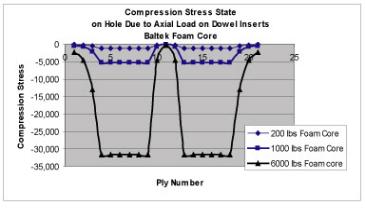 | 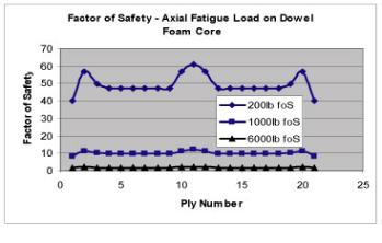 |
ANALYSIS A – Compression Stress State resulting from axial loads shows maximum compressive stress in the Dial Table Skins and virtually no stress in the foam core. The factor of safety profile shows the design was adequate for at least 1000 lbs applied repeatably for 10^6 cycles.
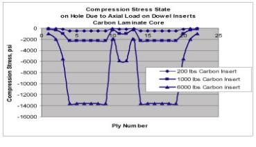 | 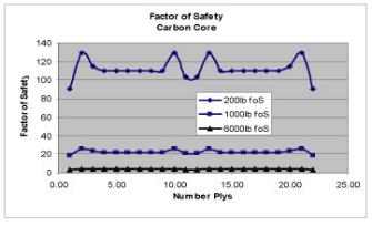 |
ANALYSIS B – Compression Stress State resulting from axial loads shows maximum compressive stress in the Dial Table Skins and compressive stress is showing in the Carbon INSERT BLOCK. The factor of safety profile shows the design was adequate for at up to 6000 lbs applied repeatably for 10^6 cycles.
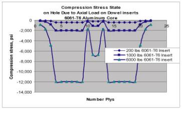 | 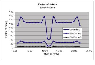 |
ANALYSIS C – Compression Stress State resulting from axial loads shows maximum compressive stress in the Dial Table Skins and compressive stress is showing in the Aluminum 6061-T6 INSERT BLOCK with a magnitude similar to that seen for the Carbon INSERT BLOCK. The factor of safety profile shows the design was adequate for at up to 6000 lbs applied repeatably for 10^6 cycles.
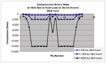 | 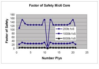 |
ANALYSIS D – Compression Stress State resulting from axial loads shows maximum compressive stress in the Dial Table Skins and compressive stress is showing in the Mic6 Aluminum INSERT BLOCK with a magnitude similar to that seen for the Carbon INSERT BLOCK. The factor of safety profile shows the design was adequate for up to 200 lbs applied repeatably for 10^6 cycles.
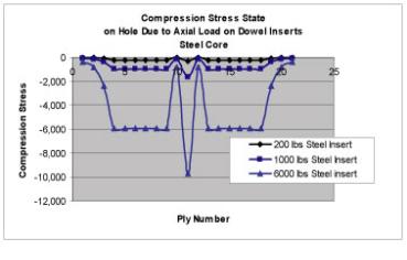 | 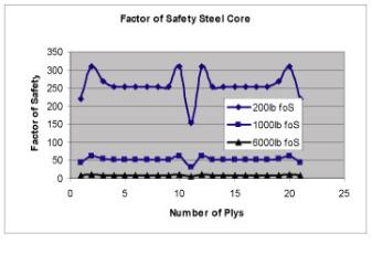 |
ANALYSIS E – Compression Stress State resulting from axial loads shows maximum compressive stress in the Steel INSERT BLOCK. The factor of safety profile shows the design was adequate for up to 6000 lbs applied repeatably for 10^6 cycles.